
Приветствую Вас,
Гость

Форумчане:
Всего пользователей
|
   |
| Форум Электроинструмент Разборка, ремонт и обзоры электроинструментов Milwaukee Перфоратор Milwaukee 2412-20 схема и ремонт (м12) |
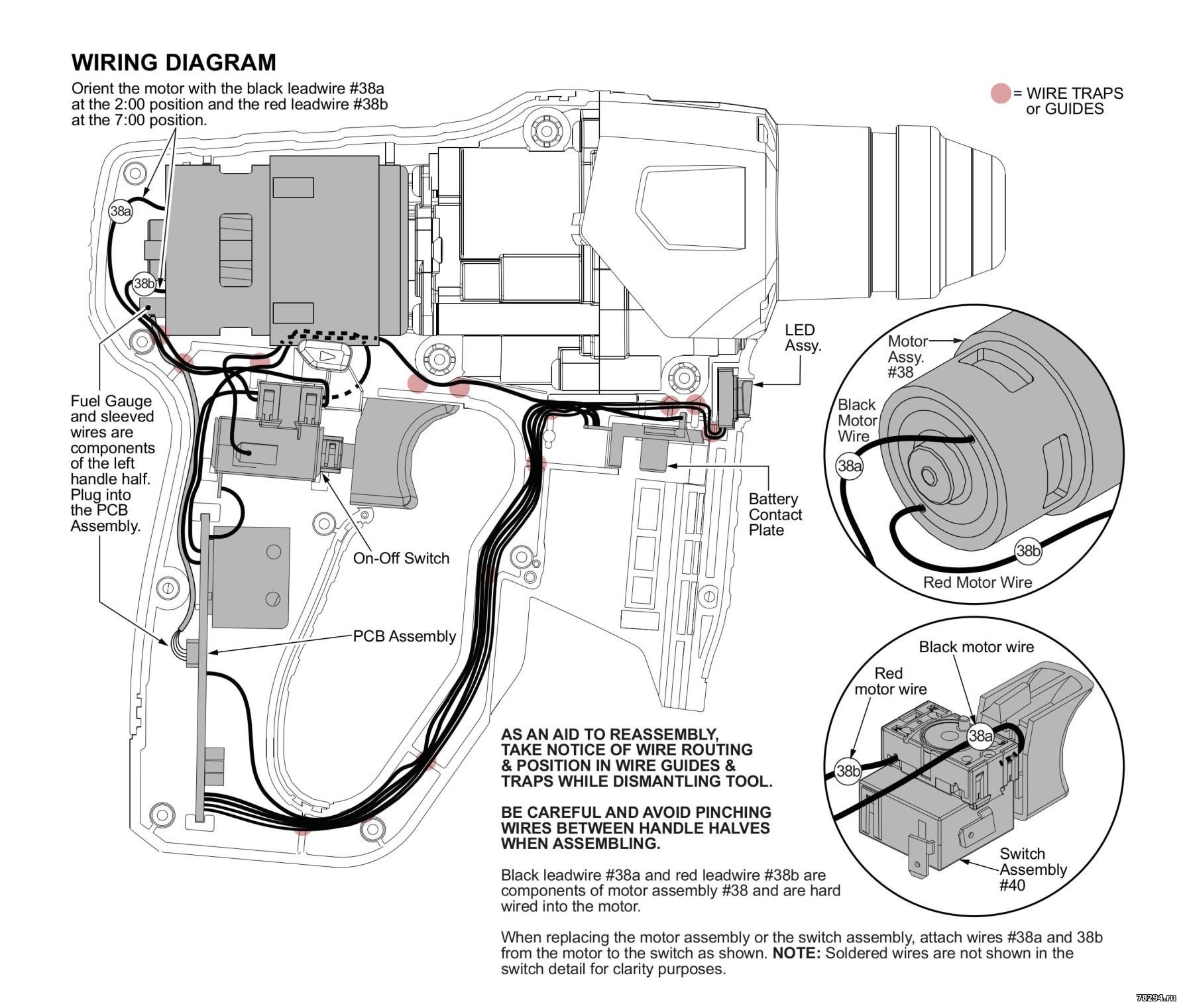
| Перфоратор Milwaukee 2412-20 схема и ремонт | |||||||||
|


| |||
| |||